The layout is controlled via a Lenz Set 100 DCC system. DCC is used to control the trains and set routes, all connected via a single power district. All points are controlled by DCC using Lenz or MERG decoders. MERG decoders are also used to drive the colour light signals via relays.
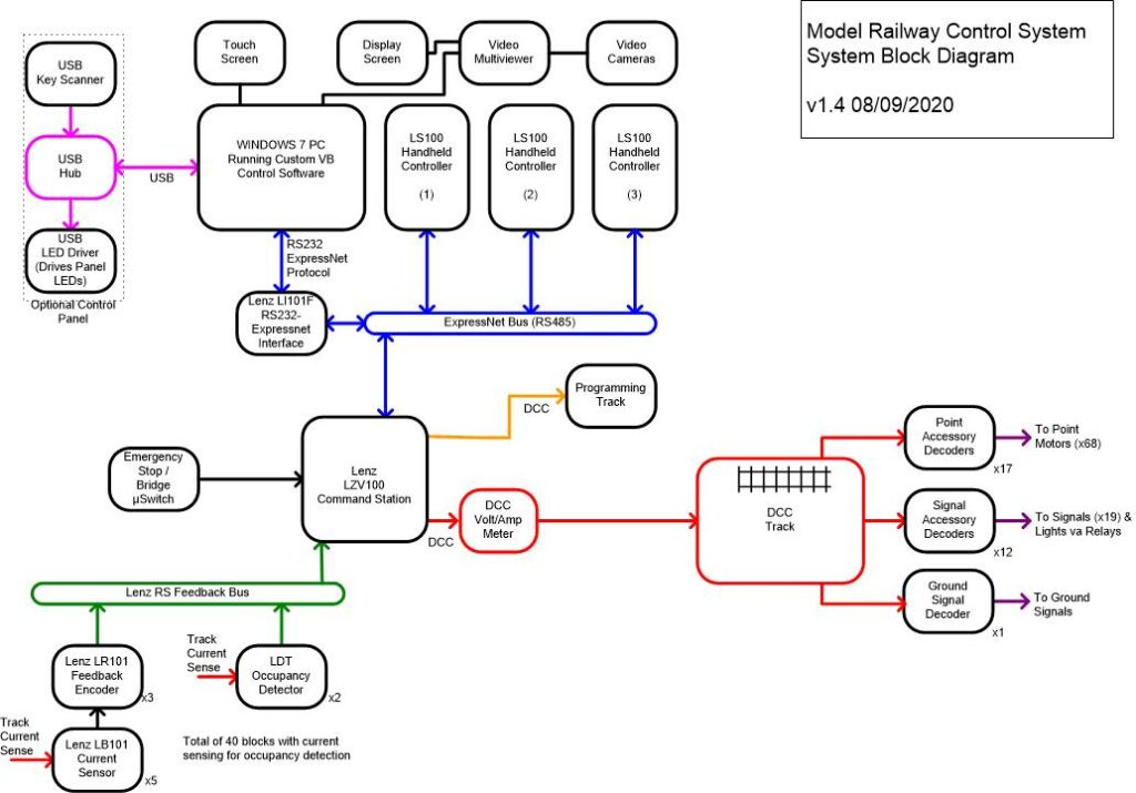
Block detection is fitted to detect where trains are using Lenz or LDT detectors which feed back via the RS bus. All of this is controlled via custom control software that I have written. The main control interface is via a touchscreen. There are a number of video cameras in the fiddle yard and these are shown on a separate monitor via a multi-view display. The following block diagram shows the main features of the control system.
The power bus is made from a double twisted pair of 22AWG wire with droppers also from 22AWG wire. There is at least one dropper to each section of track. Where detection is fitted the droppers need to be grouped together and connect back to the correct block detector.
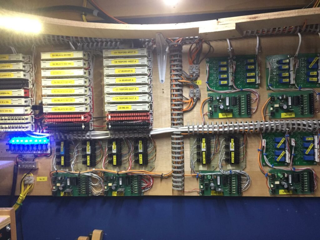
All the signal wiring is done via multicore cables and krone termination blocks mounted on a wall below the layout. There is an additional safety feature in that the access ‘scenic bridge’ has a microswitch linked to the Lenz emergency stop input which will stop all movements if the bridge is opened.
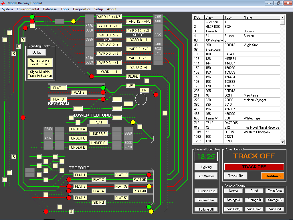
The control software is written in Visual Basic 6. As well as showing occupancy it can set routes by clicking a start and end location, similar to entry-exit routing used on the main line railway. This then sends instructions via the Lenz system to accessory decoders (MERG and some Lenz) which drive SEEP or Peco point motors fed from a 16v AC supply. By knowing about set routes and occupancy the software can also automatically control the signals. These are driven via MERG steady state decoders and relays.
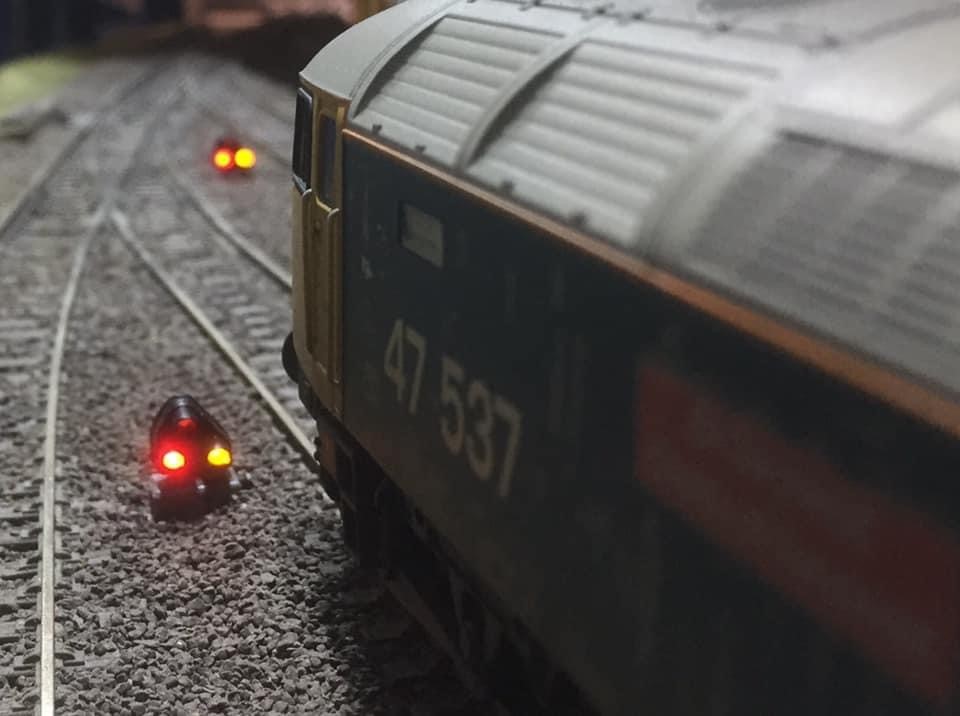
Two DCC addresses are used per signal – one is red or not, the other then denotes yellow or green. This reduces the number of addresses required and simplifies the use of common negative signals from Berko and Eckon which are wired via relays. It also means that if there if DCC power is cut, all signals go to red (they are fed from a separate 12v DC supply). DCC Concepts ground signals are fitted in some locations and these are also controlled via the control software.
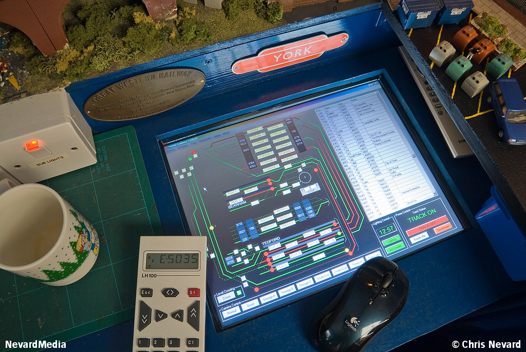
The main control touchscreen is mounted at the end of the layout on a control desk along with a rolling road that can be switched to DC, DCC or DCC Programming track. The computer software also controls the lights and can act as a loco throttle.
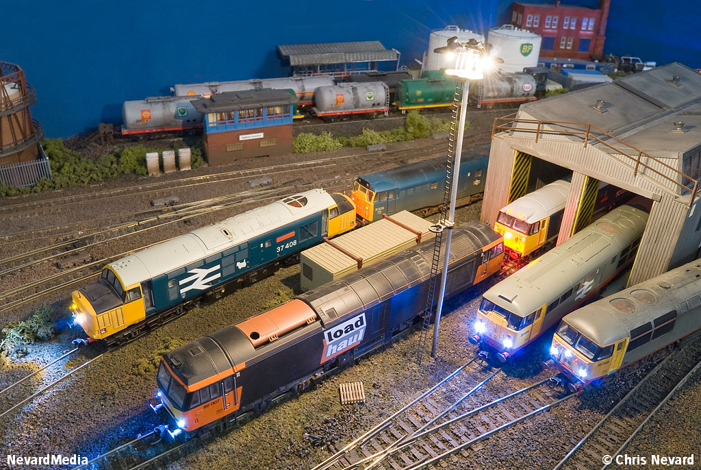
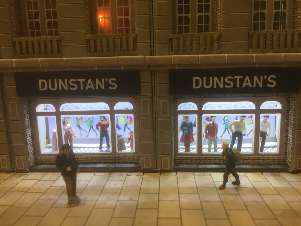
The majority of buildings are fitted with lights. These come from a variety of sources including Patronics for the station lights and Eckon for the yard lights. Other buildings use LEDs or grain of wheat bulbs.
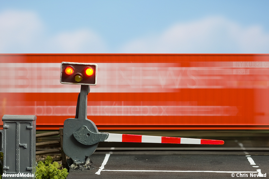
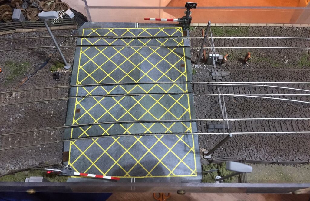
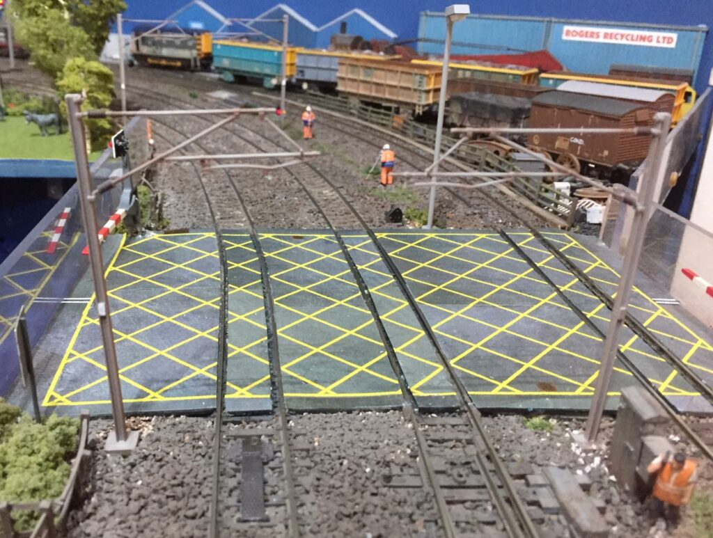
The level crossing has working lights and barriers and is activated from the control computer and interlocked with the signals. The sequence is controlled by a PIC microprocessor which drives LEDs fitted into Peco barriers directly. The barriers are moved by servo motors controlled by a MERG servo4 board which is controlled by the same PIC. There is a video of this that shows the whole operating sequence available in the gallery.
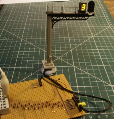
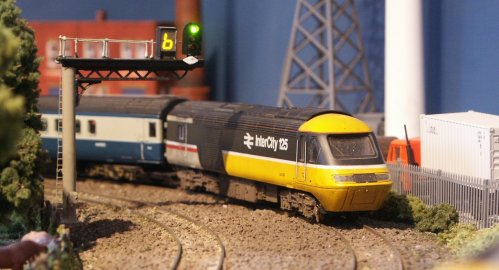
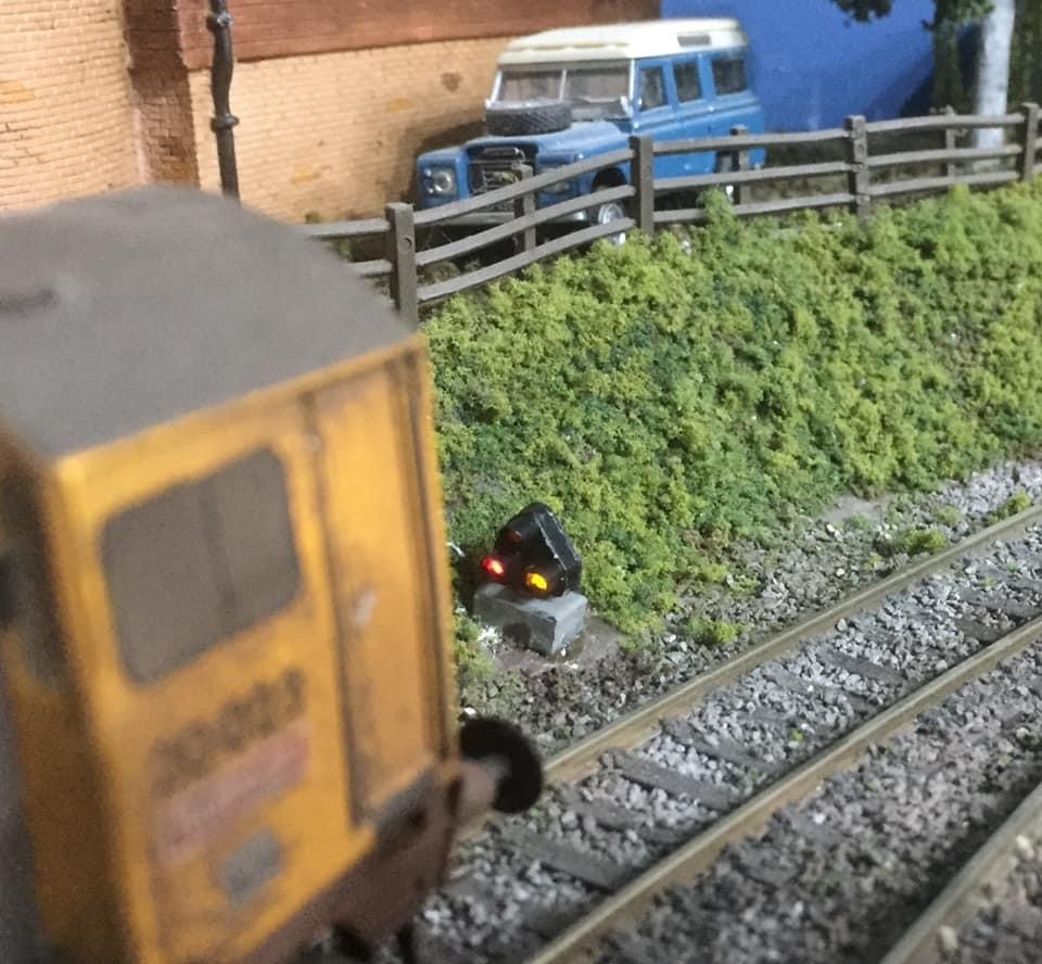
I have built two signal gantries with theatre indicators which are placed on the approaches to Tedford and also Bearham. They are not perfect scale models but give a good representation. A photograph of the prototype on my workbench is below. Construction is brass and plastic. The main signal head is an Eckon 3 aspect unit and the theatre display is built from a surface mount 7 segment display. All wiring is inside the gantry using fine kynar cable.